Tuesday 26 April 2011

Creating Objects in 2D Design


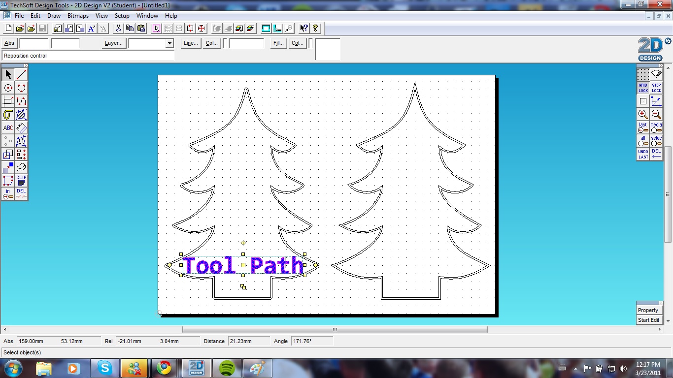
I changed the grid angle to isometric by double clicking on the grid button and clicking on the isometric option when the grid/coordinate settings window popped up.

I applied the grid lock button to gain more control over the placement of the drawing and the attachment of the lines.


Using the line tool on an isometric grid with the grid lock applied i drew the outline of a cuboid.

I then changed the grid spacing to allow me to draw the finer details of a microwave without losing control over placement and accuracy with the grid lock turned on. I did this by double clicking on the grid lock butting and changing the grid spacing of the x and y axis to 3mm instead of 10mm.

I was then able to draw the window of the microwave closer to the edge of the cuboid that i had made previously.

To create the buttons i drew an ellipse using the circle tool. I drew a circle and then dragged the dimension nodes to create the ellipse.

To extrude the ellipse to look more like a microwave knob i went to draw >3d effects> isometric.

I then changed the depth of the extrusion in the window that popped up after i had selected isometric from the 3d effects menu. I chose 3mm as this was also the same as my grid spacing.

Using the isometric grid as a guide i then clicked on the grid to create my extrusion at the correct angle.

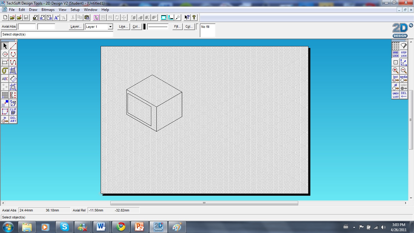
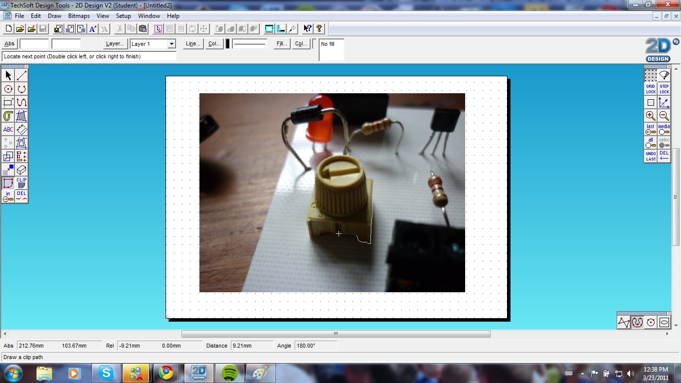
By highlighting the whole object, left clicking and dragging (with grid lock turned off) i placed the knob onto the microwave. I then press ctrl>c, ctrl>v to copy and paste another knob exactly the same. I placed this on the microwave using the same method.


To fill the knobs with solid colour, i left clicked on the face of them and selected fill from the top menu.

I then chose 'solid' from the menu, left clicked on 'colour' and chose a colour from the palette that popped up. To finish, i selected apply and ok.

I then created a square using the rectangle tool and used 3d effects> isometric to make a button shape. So that it was totally filled with colour i selected the bounding fill tool. I then chose a fill colour by selecting the 'fill' button and highliting a colour, clicking apply and ok to finish.

I zoomed in to make the unfilled parts of the object easier to select. After selecting these parts a window appeared if there were any islands in the selected area i selected 'No' and then selected the area i wished to add a fill too.

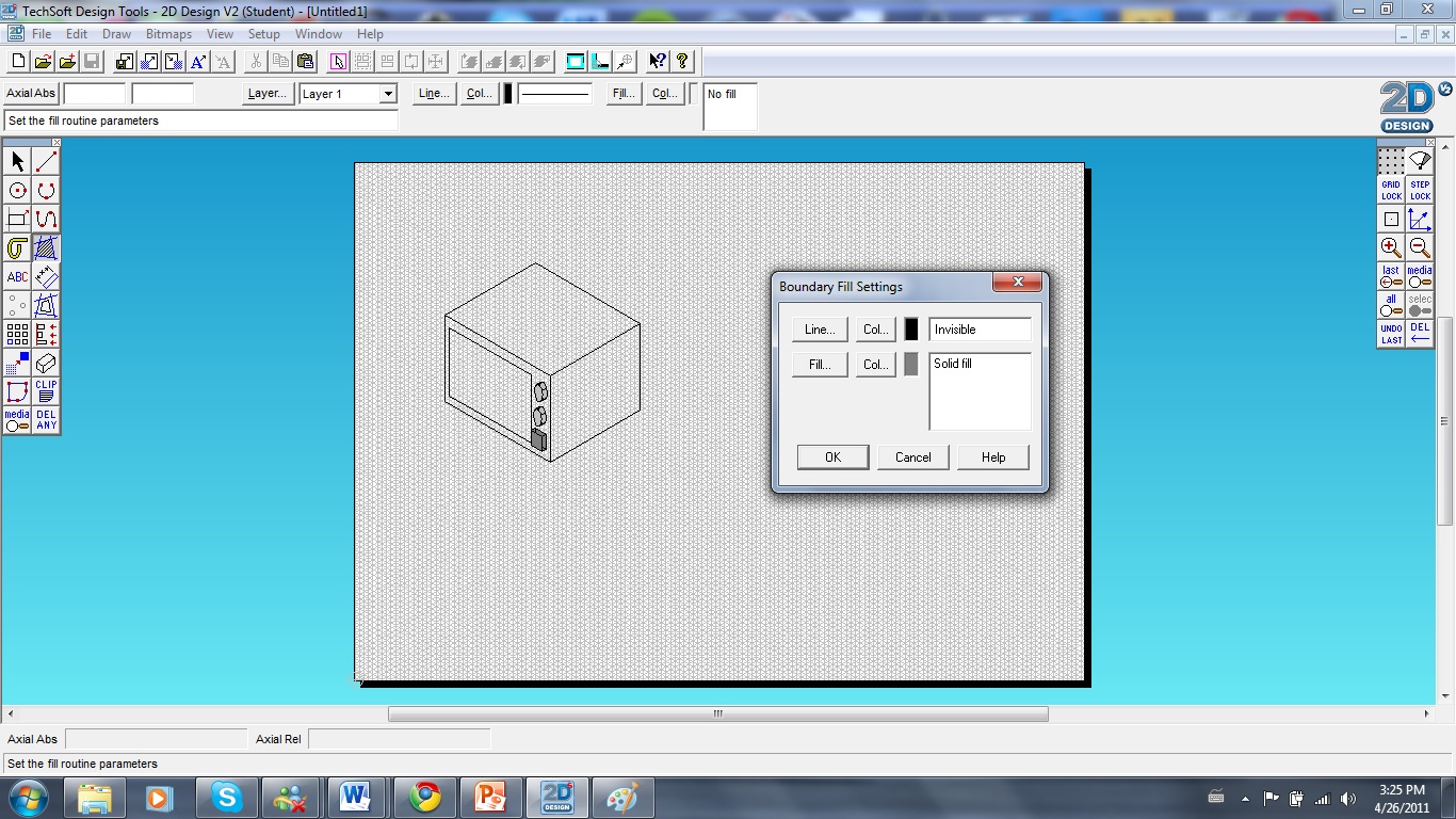
After placing the final button onto the microwave i repeated the bounding fill process on the whole of the object.

I then selected the outline of the microwave by pressing shift and selecting each individual line. Pressing shift allows you to select multiple individual objects at a time. 

I then altered the thickness of the outline by selecting the line button at the top of the change and by choosing the thick option. I chose to increase the thickness to 1mm.

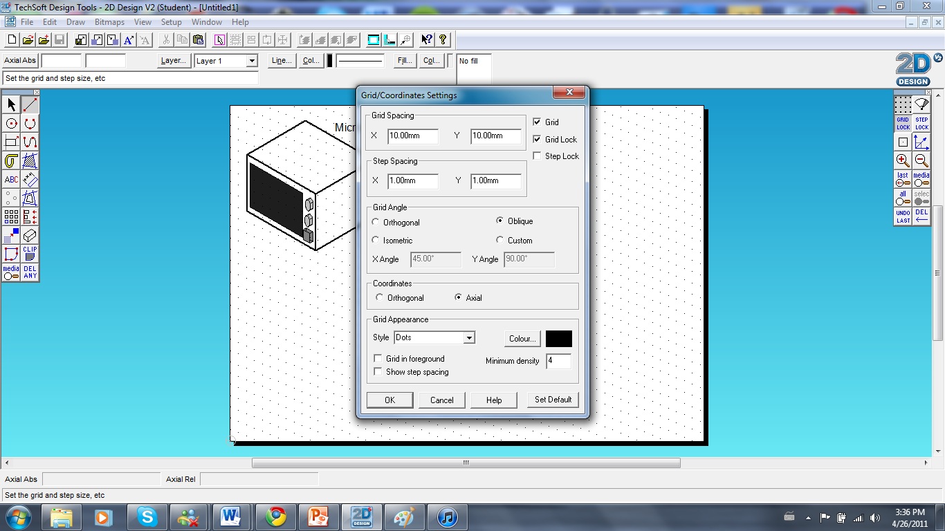
By double clicking on the 'grid lock' button i was able to select the oblique grid angle option and change my grid spacing on both axis to 10mm.

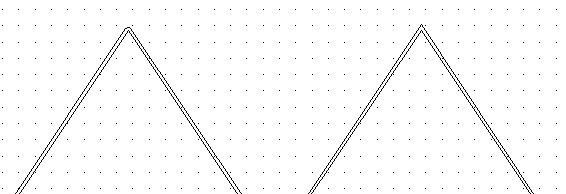
Using the line tool with grid lock on i drew a basic cuboid.


To create the curved lines i used the arc tool to draw from one side of the box to the other, using the crate that i had made as a guide.

I then selected the 'delete at nearest intersection' delete option and erased all the crating and construction lines.

I then copied and pasted the curved lines using ctrl>c and ctrl>v. I left clicked and dragged them into place to create the details of the bin.


Using the line tool i drew across from one line to the other using the grid lock and snap tool as a guide.

I then used the delete at intersection delete tool to erase the lines across the top of the bread bin. 


To draw the slits across the width of the bread bin i used the attach tool whilst also using the grid layout as a guide for the angle of the lines. 


I then used the bounding fill tool to apply solid colour to the drawing. 

When applying colour to the last slit i clicked on 'yes' when it asked me if there were any islands. This would mean that it would apply colour around the handle of the bread bin, but not in it.

After i had filled all areas of the object i selected the outline by holding shift and by selecting each line.

I then thickened the line by altering the line options found in the line settings window when clicking on the line button.

Finished microwave and bread bin!

Friday 25 March 2011

Clipping and vectorizing images in 2D design.


 First of all i imported an image. To do this i went to file > import file.


 I then chose my image and left clicked "ok".


After selecting ok, another window is opened allowing you to alter the size and position of the image. I kept these properties the same and then selected ok.


After importing the image i resized it by left clicking and holding, i then dragged my cursor across the image to select it. I selected the bottom right resizing node by left clicking and dragged the image whilst holding shift. This resized the images according to its original proportions.


After resizing the image i then selected the clip path tool from the main toolbar and chose the close curve tool from secondary menu that appeared. This would allow me to draw a smoother, more accurate clip path around the part of the image that i wanted.


 I then traced around the image by left clicking repetitively around the section i wanted. To stop tracing i double clicked.


 After i had traced the section of the image i then selected the clip tool from the main toolbar.


I then located the path i had traced by left clicking on it. A clip settings window then appeared asking me whether i would like to trim the outside or inside of the clipping path, i chose clip outside.


 This left me with the remaining part of the image that was left inside the clipping path.


 To vectorise the image i selected the "vectorise" tool from the main tool bar. I then located the image by left clicking on it.


 I vectorisation window then appeared with the option of changing the colours and the amount of them that were contained within the image. To change the amount of colours i clicked and dragged the slider below the group tolerance section. The colours could be changed by clicking on the "choose col" buttons to the right of each square of colour and then selecting from the colour pallete window that appeared. I then pressed ok to complete the vectorisation.

Aligning different objects in 2D design.


First of all i drew three random circles using the circles tool.


By left clicking and dragging across the page i highlighted all three circles.


I then selected the space tool located in the main tool bar on the left of the programme. An allignment window appeared an i chose "centre vertically" from the type section and "locate object to align to" from the location section. This would mean that i got the choice of which circle i would align the other two from.


I then selected ok to finish the alignment.

Making curved lines, using contour lines and using text in 2d Design


First of all i drew i Christmas tree shape using the line tool on an orthagonal grid, i also used grid lock to make the process quicker and easier.


I then left clicked on one of the lines and opened the start edit menu at the bottom right of the programme. To make this straight line curved i clicked "To Curve" on the start edit menu.


After clicking "To Curve", two more nodes appeared between the two original nodes that mark the beginning and end of the line.


By clicking and dragging these nodes it allowed me to bend the line that had originally been straight. After i had finished bending the line, i double clicked away from the drawing to deselect it. I then repeated this on some of the other lines.


To add nodes so that the line can be bent at different places i selected the line, opened the start edit menu and left clicked on to curve. I then left clicked on "add node" twice, located in the start edit menu. This split the line up into 3 equal sections.


Using the grid lock function to make sure that both of the lines were curved equally, i left clicked on the nodes that i had created and dragged them downwards 20mm.


By doing this, the lines from the base of the tree had overlapped with those i had just curved. To delete the overlapping lines i left clicked and held down the "Del" button from the main menu. I then selected the "delete part of an object between the nearest two intersections" option that appeared in a horizontal menu.


Using my cursor i then located and left clicked in the part of the lines that were overlapping. This deleted the lines to where they had overlapped.


I finished the tree by curving the rest of the vertical lines that i had left straight. I did this by selecting each line using the "To Curve" function located in the start edit menu.


After i had finished my tree, i went on to adding a contour line. This tool is used to draw an outline around an object taking into consideration the width of the tool or machine that it is going to be cut by. The "contour" tool can be found in the main tool bar on the left of the programme.


After selecting the tool a window pops up with options of the type of tool path you want to use and the width of the gap between the object and the contour line, you can also change the amount of contour lines that you apply to the drawing. Here i have chosen "Tool Path" and 2mm as my contour spacing keeping 1 as my number of contours. I then selected ok.


To apply the contour line i left clicked on the outline of the object.


To finish the design ready to be cut out as a whole object i deleted the lines that ran through the bottom of the design. I did this by using the  "delete part of an object between the nearest two intersections" delete option which can be found when left clicking and holding the delete button found in the main tool bar on the left of the programme.


To make a graphical path contour i copied and pasted my tree, using "Ctrl-C" and "Ctrl-V". I then selected the contour tool and changed the path to graphical. I also changed the contour spacing to 2mm to be able to get a proper comparison between the two.


The difference between the two lines is that the tool path makes a rounded edge around the object where as the graphical draws an identical path.


To add text to the design i selected the "ABC" button located in the main toolbar on the left of the programme.


I then located the area in which i wanted to place my text and wrote the desired text in the window that appeared. By left clicking on the "Settings" button it allowed me to edit the font, size, colour and placement of my text.


To change the line colour of my text i left clicked on the "col" button in the attributes section of the editing window and selected a colour from the pallete that appeared.I then clicked ok to finish editing.


To resize the text i had created i first selected it, then i held down shift and left clicked and dragged the top right resizing node. This allowed me to scale the text to its original proportions.


To position the text i left clicked and held down on it and then dragged it to the desired position.